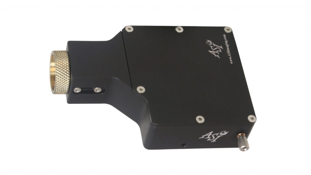
CRISP Autofocus System
The CRISP system is designed to maintain focus over time, i.e. compensate for thermal and other factors that may cause the sample to drift out of focus over time. It also can be used to maintain a given focal point while scanning the sample in XY. If you are looking to find the optimal focal point while scanning through the sample in Z please see our video autofocus system.
Please Note:
CRISP will not work with index matching mounting media. This is how most prepared slides are made. There is no interface with a refractive change near the sample to reflect the light. CRISP relies on reflected light from the sample to detect focus position. Often the reflected light comes from small refractive index discontinuities at sample surfaces. The amount of light reflected at a dielectric interface is given by: R=(n1-n2)^2/(n1+n2)^2
Where n1 and n2 are the reflective indexes of the adjoining dielectric materials. There must be a difference between the refractive indexes in order for CRISP to work.
CRISP System Details
- Mounts onto any microscope’s standard C-Mount port
- Maintains ideal focus for days
- Works with most normal microscope objectives
- Low noise electronics allows locking to glass/water interfaces
- Integrates with ASI Piezo-Z or motorized focus stages
- Simple post-lock fine adjustment of focus
- Automated control
Adjustments, Options and Control
- Built-in C-Mount extension for optical offsets
- LED beam iris to match illumination beam to objective pupil for optimum performance
- Lateral detector adjustment
- LED colors from 625-1050 nm
- LED intensity control
- Programmable gain and averaging functions to optimize system for stability or speed
CRISP Specifications
| Light Source | LED |
| Wavelength | Choose from 625-1050 nm |
| Optical Interface | C-Mount |
| Typical Focus Accuracy | <5% of objective Depth of Focus |
| Controller | MS-2000 w/ CRISP card TG-1000 w/ CRISP card |
Theory of Operation
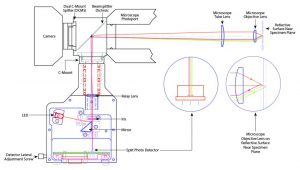
The CRISP system projects the image of a mask illuminated with an IR LED into the sample plane. Only one half of the objective pupil is illuminated. This means that the point spread function of the objective is highly skewed, so that the reflected image of the mask will move laterally as focus is changed. CRISP detects this lateral motion of the LED image to obtain a focus error that is used to close the focus positioning loop.
Installation
CRISP is usually installed with an ASI’s Dual C-Mount Splitter (DCMS) that contains the required dichroic beam combiner and blocking filters and provides the C-Mount port for the camera.

Mit dem Laden des Videos akzeptieren Sie die Datenschutzerklärung von YouTube.
Mehr erfahren
Newsletter
Be the first to get all the information about new products in our range and find out the latest research results in microscopy in our free newsletter.


